Automotive Multioutput Voltage Regulator
A8450
5
Allegro MicroSystems, LLC
115 Northeast Cutoff
Worcester, Massachusetts 01615-0036 U.S.A.
1.508.853.5000; www.allegromicro.com
Characteristics
Symbol
Test Conditions
Min.
Typ.
Max.
Units
Protection
NFAULT, NPOR Output Voltage
V
ERRON
Fault asserted;
I
NFAULT
, I
NPOR
= 1 mA
400
mV
NFAULT, NPOR Leakage Current
I
ERROFF
V
NFAULT
, V
NPOR
= 5 V
1
糀
POR Delay
t
POR
C9 = 0.47 糉
65
100
135
ms
V33 Undervoltage Threshold
V
UVLOV33
V
33
rising
2.80
2.95
3.10
V
V
33
falling
2.75
2.90
3.05
V
V33 Hysteresis
V
HYSV33
80
mV
V5A, V5D Undervoltage Threshold
V
UVLOV5
V5A, V5D rising
4.36
4.50
4.75
V
V5A, V5D falling
4.24
4.38
4.63
V
V5A, V5D Hysteresis
V
HYSV5
125
mV
VADJ Undervoltage Threshold
V
UVLOVADJ
V
FB
rising
1.02
1.07
1.12
V
V
FB
falling
0.97
1.02
1.07
V
VADJ Hysteresis
V
HYSVADJ
At FB pin
70
mV
VADJ, V33 Overcurrent Threshold
V
OC
175
200
225
mV
VREG Undervoltage Threshold
V
UVLOVREG
4.94
5.15
5.36
V
Thermal Warning Threshold
T
JTW
T
J
rising
160
癈
Thermal Shutdown Threshold
T
JTSD
T
J
rising
175
癈
Thermal Shutdown Hysteresis
T
HYSTSD
Recovery period = T
JTSD
T
JTW
15
癈
*Linear regulator output specifications are only valid when V
REG
is in regulation (V
BB
e 6.5).
ELECTRICAL CHARACTERISTICS (continued) at T
A
= 40篊 to 135癈, V
BB
= 6 to 45 V, V
ENB
= 5 V, unless
otherwise noted
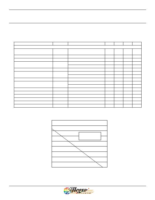
Ambient Temperature (癈)
0.0
0.5
2.0
2.5
3.0
3.5
4.0
4.5
1.0
1.5
20
40
60
80
100
120
140
160
Power Dissipation Versus Ambient Temperature
4-Layer PCB*
(R
窲A
= 35 篊/W)
*In still air; mounted on PCB based on JEDEC high-conductance standard PCB
(JESD51-7; High Effective Thermal Conductivity Test Board for Leaded Surface Mount
Packages); data on other PCB types is provided on the Allegro Web site.
发布紧急采购,3分钟左右您将得到回复。
相关PDF资料
AD595CD
IC THERMOCOUPLE INSTR AMP 14CDIP
AD597AHZ
IC THERMOCOUPLE COND TO-100-10
AD7314ARMZ-REEL7
IC SENSOR TEMP 10BIT DGTL 8-MSOP
AD7814ARTZ-REEL
IC TEMP SNSR 10BIT DGTL SOT23-6
AD7818ARZ
IC ADC 10BIT W/TEMP SENSOR 8SOIC
AD8210WYRZ-R7
IC CURRENT MONITOR 0.5% 8SOIC
AD8211YRJZ-R2
IC CURRENT MONITOR 0.25% SOT23-5
AD8213WYRMZ
IC CURRENT MONITOR 0.25% 10MSOP
相关代理商/技术参数
A845DSC
制造商:Pentair Technical Products / Hoffman 功能描述:DSC Box 8.00x4.00x4.75 Gray, 8.00x4.00x3.75, Steel
A-845DSC
制造商:Pentair Technical Products / Hoffman 功能描述:DSC Box 8.00x4.00x4.75
A845JFGQRR
制造商:Pentair Technical Products / Hoffman 功能描述:Enclosure 8.00x4.00x5.00 , 7.50x4.00x5.02, Fiberglass
A-845JFGQRR
制造商:Pentair Technical Products / Hoffman 功能描述:Enclosure 8.00x4.00x5.00
A845JFGR
制造商:Pentair Technical Products / Hoffman 功能描述:Enclosure 8.00x4.00x5.00 , 7.50x4.00x4.94, Fiberglass 制造商:Hoffmann/Pentair 功能描述:
A-845JFGR
制造商:Pentair Technical Products / Hoffman 功能描述:Enclosure 8.00x4.00x5.00
A845ZTG510
制造商:ON Semiconductor 功能描述:
A84617
制造商: 功能描述: 制造商:undefined 功能描述:
